Introduction to EDFA Optical Amplifiers
EDFA optical amplifiers (Erbium-Doped Fiber Amplifier) are key components of modern fiber-optic transmission systems used in the deployment and operation of optical backbone networks. EDFA amplifiers are most widely used in DWDM equipment.
EDFA amplifiers are devices that amplify an optical signal directly in the optical fiber without converting it into an electrical signal. This allows compensation for signal losses in fiber-optic lines and enables long-distance data transmission without the need for regeneration.
EDFA operates based on fiber doped with erbium ions (Er³⁺). The operating principle is based on stimulated emission: erbium ions absorb pump energy and then transfer this energy to the signal, amplifying it. EDFA is typically used in DWDM systems in the C-band (1528–1565 nm), where losses in standard single-mode fiber (G.652) are minimal (about 0.2 dB/km). Thanks to this, EDFA amplifiers are nearly ideal for backbone, regional, and metropolitan networks, providing high bandwidth and reliability.
EDFA amplifiers are required when the optical signal weakens due to fiber attenuation, scattering effects, or losses in passive components (multiplexers, connectors, splices, etc.). Without EDFA amplifiers, the transmission distance from active equipment is usually limited to 80–100 km, whereas with EDFA the link length can reach thousands of kilometers. For example, in DWDM systems, EDFA allows simultaneous amplification of up to 96 channels while minimizing noise and signal distortion.
Operating Principle of EDFA
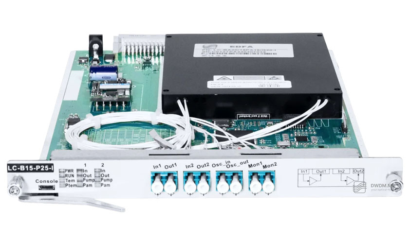
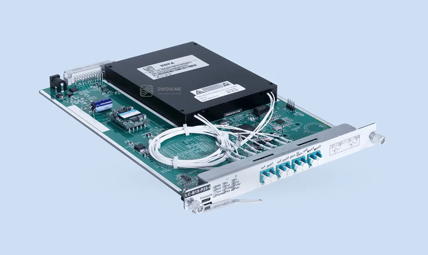
Typically, an EDFA consists of the following components:
erbium-doped fiber (EDF);
pump laser (usually 980 nm or 1480 nm);
optical isolator;
multiplexer for combining the signal and pump light;
noise suppression filters.
The EDFA operating process can be divided into the following stages:
- Pumping – the pump laser emits light at wavelengths of 980 nm (for fast excitation) or 1480 nm (for more efficient energy use). As a result, erbium ions in the fiber absorb this energy and transition from the ground state (⁴I₁₅/₂) to the excited state (⁴I₁₃/₂, via the intermediate ⁴I₁₁/₂ level at 980 nm).
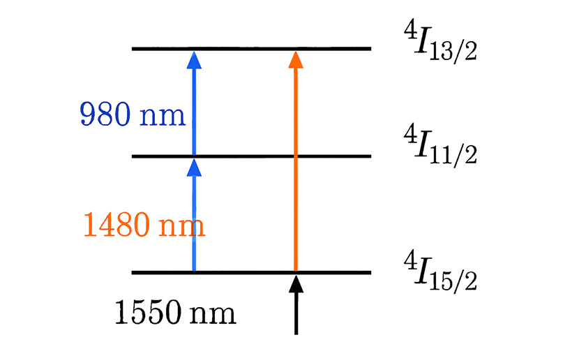
- Population inversion – with sufficient residual pump power (typically 100–500 mW), a population inversion is created, where more ions are in the excited state than in the ground state. This is a necessary condition for signal amplification.
- Stimulated emission – the propagating optical signal (around 1550 nm) stimulates excited erbium ions to return to the ground state, emitting photons with the same wavelength, phase, and direction as the signal, resulting in optical signal amplification.
- Noise suppression (filtering) – optical isolators prevent backward propagation of amplified spontaneous emission (ASE), which is the main source of noise in EDFA amplifiers.
The use of EDFA amplifiers offers several advantages:
high gain (up to 30–40 dB);
low noise figure (3–5 dB);
polarization independence;
ability to amplify multiple channels simultaneously.
However, EDFA amplifiers are sensitive to input power. In case of overload, saturation occurs, and amplification outside the C/L bands is not possible without special modifications.
When and Where to Use EDFA
EDFA amplifiers are used when signal losses exceed the system power budget (long link distance, a large number of splices or passive components, etc.):
long-haul optical links – in backbone networks to compensate for attenuation over distances greater than 80 km, where without amplification the signal fades and OEO regeneration is required, which is costly and reduces speed due to conversions;
DWDM systems – for simultaneous amplification of many channels (up to 96) without separation. EDFA is usually integrated with multiplexers, providing capacity of 1.6 Tbps and higher;
data center interconnections – when connecting remote data centers that require high data rates (100G/400G/800G) and low latency;
metropolitan and regional networks – to expand the capacity of existing fibers without deploying new ones.
EDFA is usually not used on short optical links (up to 40 km), where high-power optical transceivers are sufficient. However, in complex topologies with many passive elements (splitters, OADM, etc.), the use of EDFA amplifiers becomes almost inevitable.
Types of EDFA Optical Amplifiers and Their Applications
In technical literature, EDFA amplifiers are classified based on their position in the optical link:
Booster Amplifier (BA) – installed immediately after the optical transmitter to increase output signal power (up to +20 dBm) and compensate initial losses. Used when the signal entering a long link is weak or in systems with a high channel count. For example, in DWDM systems with 40+ channels, a booster prevents OSNR degradation.
In-line Amplifier (LA) – placed in the middle of the optical link to compensate for fiber attenuation (typically every 80–100 km). Provides 20–25 dB gain and maintains signal level. Ideal for backbone routes requiring multiple amplification stages without regeneration. In combination with dispersion compensation units (DCU), it enables transmission over distances of up to 1000–2000 km.
Pre-Amplifier (PA) – installed before the optical receiver and provides 25–30 dB gain, improving receiver sensitivity and reducing BER. Used at the end of the link where the signal is weak or in systems with a low optical power budget.
In some cases, combined configurations are used, such as BA+PA in point-to-point (P2P) links.
The choice of EDFA type primarily depends on the optical budget. For example, a 100 km link with 20 dB attenuation can use an in-line amplifier, while a 200 km link requires a combination of a booster and an in-line amplifier.
DWDM.ME offers EDFA amplifiers integrated with the MU-series platform. EDFA amplifiers manufactured by DWDM.ME support 980/1480 nm pumping, optical gain up to 30 dB, and low noise figure (NF < 5 dB). This makes them nearly ideal solutions for DWDM systems with 80+ channels.
Basic EDFA Calculations
For designing EDFA-based systems, the following simple calculations are useful.
- Gain (G):
G = 10·log₁₀(Pout / Pin),
where Pout is output power and Pin is input power (in mW).
Example:
If Pin = 0.1 mW and Pout = 10 mW,
G = 10·log₁₀(100) = 20 dB.
This shows the level of signal amplification. - Noise Figure (NF):
NF = 10·log₁₀(SNRin / SNRout),
where SNR is the signal-to-noise ratio.
The ideal NF is about 3 dB; in practice, 4–6 dB.
Example:
If SNRin = 40 dB and SNRout = 35 dB,
NF = 5 dB.
A high NF degrades signal quality over long distances. - Link Budget:
Total budget = Ptx + G_EDFA − Losses − Margin,
where Ptx is transmitter power,
Losses are total losses (fiber + all components),
Margin is the safety margin (5–10 dB).
Example:
Ptx = 0 dBm,
G_EDFA = 25 dB,
Losses = 30 dB (150 km × 0.2 dB/km),
Margin = 5 dB.
Budget = 0 + 25 − 30 − 5 = −10 dBm.
If receiver sensitivity is better than −20 dBm, the system will operate correctly. - Pump Power:
To achieve G = 25 dB, approximately 200 mW of pump power is required.
A simplified estimation formula:
G ≈ η·Ppump / (h·ν·A),
where η is efficiency,
hν is photon energy,
A is the fiber core cross-section area (single-mode fiber 9/125 µm, where 9 µm is the core diameter).
In real systems such as the MU-series from DWDM.ME, built-in monitoring systems allow real-time parameter adjustment.
Real-World EDFA Use Cases
- Backbone DWDM Network:
In a project connecting two nodes 500 km apart, a booster amplifier is installed after the multiplexer, in-line EDFA amplifiers are placed every 100 km, and a pre-amplifier is installed before the demultiplexer. Using the MU-380 chassis (5U, 20 slots) enables 1.6 Tbps over 96 channels. EDFA amplifiers compensate for 100 dB of losses, ensuring BER < 10⁻¹². - Data Center Interconnection:
Three data centers in different cities are interconnected using MU-series equipment and EDFA amplifiers. A booster amplifies the signal at the multiplexer output, in-line amplifiers are installed at intermediate nodes, and a pre-amplifier improves the received signal. Transmission distance reaches up to 1000 km without regeneration, with optional integration of optical line protection (OLP) switches for 1+1 or 1:1 redundancy. - Regional Provider:
For a CWDM/DWDM link of 80–100 km, in-line EDFA amplifiers integrated with the MU-70 (1U) platform are used.
Example: a 4×100G muxponder with an EDFA amplifier allows capacity expansion without deploying new fibers.
EDFA Integration with the MU-Series Platform
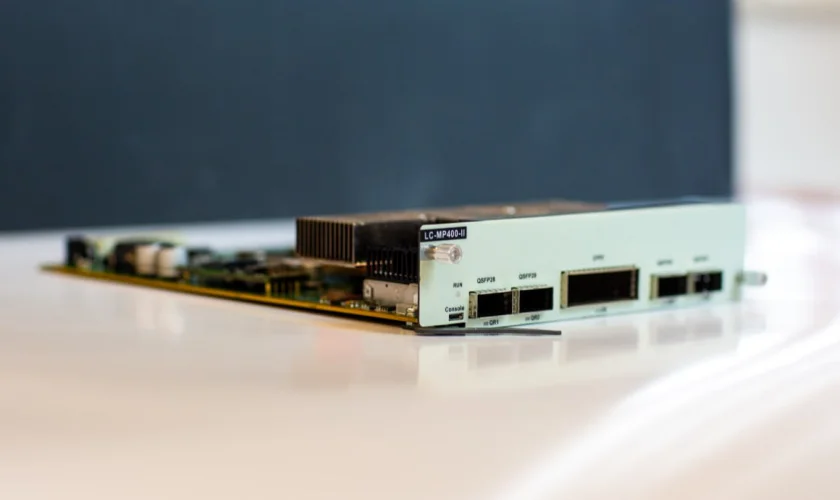
The MU-series platform by DWDM.ME is a modular system for building DWDM networks, where EDFA amplifiers are installed in the same chassis as line cards and service modules. The MU-180 chassis (2U, 8 slots) allows combining EDFA with transponders (LC-MP100-II) and optical switches (OLP). This solution provides scalability from 10G to 400G. In addition, DWDM.ME control boards enable online monitoring of OSNR and signal power at both transmitter and receiver.
Conclusion
EDFA optical amplifiers are the foundation of modern optical networks, enabling cost-effective and efficient data transmission and allowing the deployment of long-distance optical links with relatively low capital expenditure. The use of EDFA amplifiers makes it possible to expand existing DWDM systems.
On our website https://dwdm.me/ you will find all the necessary information about EDFA amplifiers and MU-series transmission platforms for solving tasks ranging from metropolitan to backbone networks. If required, our specialists are always ready to help you select the right equipment and provide professional consultation.