In the era of digital transformation, fiber-optic communication systems have become the foundation for long-distance data transmission. With the growing demand for high-speed internet, cloud computing, and streaming services, backbone providers and telecom operators are striving to increase bandwidth and extend transmission distances while minimizing signal loss. Optical amplifiers play a key role in this process, and among them, Raman amplifiers stand out due to their efficiency in ultra-long-haul systems ( https://dwdm.me/blog/use-edfa-optical-amplifiers/).
What Raman amplifiers are and when they should be used
Raman amplifiers (also known as stimulated Raman scattering amplifiers) are devices that amplify optical signals directly within the fiber by means of the Raman effect. This effect was discovered by Indian physicist Chandrasekhara Venkata Raman in 1928 and is based on the nonlinear interaction between light and the molecules of the medium. In simple terms, a high-power pump laser transfers energy to a weaker signal, increasing its intensity.
Unlike erbium-doped fiber amplifiers (EDFA), Raman amplifiers do not require specially doped fiber-they operate in standard single-mode silica fiber. Amplification occurs due to a frequency shift, where energy from a shorter-wavelength pump (for example, 1425-1465 nm) is transferred to a longer-wavelength signal with a shift of about 13 THz (approximately 100 nm in the C-band, 1530-1565 nm).
Raman amplifiers are used when standard EDFA amplifiers are not sufficiently effective, namely:
in ultra-long spans (over 100-200 km), where accumulated noise from multiple EDFAs degrades the optical signal-to-noise ratio (OSNR);
in DWDM systems with 40 or more channels that require broadband amplification (up to 100 nm);
to reduce nonlinear distortions (such as four-wave mixing) and noise, especially in submarine backbone cables or long-haul networks;
when it is important to reduce the number of intermediate regeneration sites, thereby lowering operational costs.
For example, with a fiber attenuation of 0.2 dB/km, a 500 km link results in 100 dB of loss-making transmission over such a distance practically impossible without amplification. Raman amplifiers distribute gain along the entire fiber length, improving OSNR.
Theory of operation of Raman amplifiers
The operation is based on stimulated Raman scattering (SRS). High-power pump light (1-2 W at multiple wavelengths) is injected into the fiber, exciting silica molecules. This causes scattering, in which pump energy is transferred to signal photons, thereby amplifying the useful signal. The Raman gain coefficient (gR) is typically 6×10⁻¹⁴ m/W for single-mode silica fiber in the C-band. The effective interaction length (Leff) is:
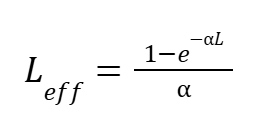
where α is the attenuation coefficient (0.2 dB/km ≈ 0.046 km⁻¹), and L is the fiber length.
The effective mode area of the fiber is approximately Aeff ≈ 50-80 μm².
Signal amplification in Raman amplifiers is distributed almost along the entire fiber length. As a result, the level of noise associated with amplified spontaneous emission (ASE) is significantly reduced. Consequently, the noise figure (NF) of Raman amplifiers is typically around 3-5 dB, which is noticeably better than the 5-7 dB of conventional EDFA amplifiers. An additional advantage is the wide gain spectrum due to the amorphous structure of silica, with a characteristic peak at a frequency shift of about 13.2 THz.
Types of Raman amplifiers and their applications
Raman amplifiers are classified by design and pump direction:
Distributed Raman Amplifier (DRA) – pumping is performed in the transmission fiber; most effective for long-haul links;
Forward-pumped – pumping is in the same direction as the signal, reducing input noise but potentially introducing nonlinear effects; used for spans up to 100 km to improve OSNR;
Backward-pumped – pumping is opposite to the signal direction, resulting in lower nonlinearities; typically used for spans of 200 km or more and is standard for backbone networks;
Bi-directional pumping – pumping is applied in both directions to balance gain and noise; used in high-power systems;
Discrete Raman Amplifier – amplification is performed in a short section of fiber (5-20 km) with increased gain coefficient (e.g., germanium-doped fiber); used as a booster or preamplifier at nodes when distributed amplification is not feasible.
The choice of Raman amplifier type depends on specific design requirements. For long-haul links of approximately 300-500 km, the optimal solution is a backward-pumped distributed Raman scheme (DRA), which compensates for signal attenuation along the entire fiber length while minimizing noise.
In DWDM systems with more than 80 channels, combined amplification schemes are advisable to ensure a more uniform spectrum. When used together with EDFA amplifiers, Raman amplifiers in DRA configuration are often applied as preamplifiers, reducing the overall noise figure and improving transmission quality.
Basic calculations for Raman amplifiers
Consider an example of a distributed Raman amplifier for a 100 km link. Given:
attenuation α = 0.2 dB/km ≈ 0.046 km⁻¹,
pump power Ppump = 500 mW,
Raman gain coefficient gR = 6×10⁻¹⁴ m/W,
effective area Aeff = 80 μm² = 8×10⁻¹¹ m².
The effective interaction length:
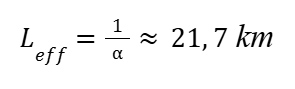
Gain:
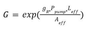
Substituting values:
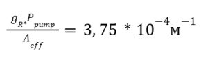
G=exp 3,75*10-4*21700 =exp 8,14 ≈3420 (≈35 дБ)
This gain compensates for approximately 20 dB loss over 100 km.
The noise figure for a backward DRA scheme:
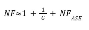
where NF_ASE ≈ 3 dB, giving NFASE≈4 дБ.
The optical signal-to-noise ratio (OSNR) is:
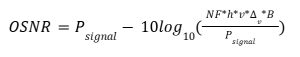
At Psignal = 0 dB:
OSNR ≈ 22 dB
This corresponds to BER ≈ 10⁻¹².
These calculations show that Raman amplification can significantly extend transmission distance compared to EDFA-only solutions.
Combined use of Raman amplifiers and EDFA
To achieve optimal performance, Raman amplifiers are often used together with EDFA amplifiers. EDFAs provide high gain in the C-band (up to 35 dB) but introduce higher noise. Raman amplifiers complement them by providing distributed gain and lower noise.
Typical configuration:
EDFA booster at the transmitter;
backward DRA along the fiber;
EDFA preamplifier at the receiver.
Such solutions improve OSNR by 3-6 dB and enable transmission distances up to 2000 km without regeneration.
Applications
Examples include:
Long-haul backbone networks – a 500 km link, DWDM with 40 channels at 100G each: a backward-pumped Distributed Raman Amplifier (DRA) with pump power of 1 W is used, compensating for 15-20 dB of attenuation. When combined with EDFA amplifiers deployed every 80 km, this approach makes it possible to reduce the number of EDFA units from 6 to 3;
Submarine cable systems – Raman amplifiers are used in transatlantic backbone systems, where spans of 100-150 km achieve an OSNR above 25 dB, allowing a significant reduction in the number of intermediate regeneration nodes;
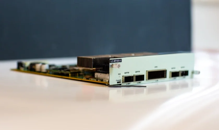
Hybrid solutions based on MU-series chassis – where an EDFA booster (24 dBm) is installed on the transmitting side, an external DRA is deployed along the optical fiber, and an EDFA pre-amplifier is used on the receiving side. This configuration allows increasing the transmission distance for 100 Gbit/s from 1000 km (when using only EDFA amplifiers) up to 1500 km when using combined amplification (joint use of EDFA and Raman amplifiers).
Real-world examples
Submarine data transmission systems with hybrid amplification – most transoceanic cables, including the historical TAT-14 and modern projects such as SEA-ME-WE, use hybrid Raman-EDFA schemes. This makes it possible to implement spans longer than 100 km and achieve total capacities of up to 100 Tbps. Raman amplifiers reduce noise levels and enable operation with more than 100 DWDM channels.
European and Asian broadband networks – in large-scale backbone projects, for example in pan-European networks, the combination of Raman and EDFA amplifiers enables data transmission over distances of up to 2000 km without signal regeneration, while supporting systems with up to 96 channels.
Since the early 2000s, manufacturers of active DWDM equipment have been offering commercial solutions based on hybrid Raman-EDFA amplifiers with a gain bandwidth of around 100 nm. In regional fiber-optic networks, such a combination makes it possible to double transmission capacity and reduce the noise figure by approximately 5 dB. The MU-series platform by DWDM.ME is designed around EDFA amplifiers with a noise figure (NF) below 5 dB and supports backbone links spanning thousands of kilometers. At the same time, the system is compatible with external DRA solutions, enabling the deployment of hybrid systems for 96 channels over distances up to 2000 km, extending the spectrum into the L-band and reducing the noise figure to as low as 3 dB.
Submarine systems with hybrid amplification-most transoceanic cables, including TAT-14 and SEA-ME-WE, use Raman-EDFA hybrid schemes. Pan-European networks-combined Raman and EDFA enable transmission up to 2000 km without regeneration. Commercial systems-since the 2000s, vendors have offered hybrid solutions with ~100 nm bandwidth.
| Scenario | Technology | Effect |
|---|---|---|
| Submarine systems (TAT-14, SEA-ME-WE) | Hybrid Raman-EDFA | Spans >100 km, capacity up to 100 Tbps, support for 100+ DWDM channels, reduced noise |
| European and Asian broadband networks | Raman + EDFA | Up to 2000 km without regeneration, systems with up to 96 DWDM channels |
| Commercial networks | Hybrid Raman-EDFA, ~100 nm bandwidth | Since 2004: doubled capacity, ~ 5 dB reduction in noise figure (NF) |
| Regional fiber-optic networks | Raman + EDFA | Increased capacity, reduced noise |
| Integration with DWDM.ME | EDFA (NF <5 dB) + external Raman DRA | 96 channels over 2000 km, spectrum extension to L-band, NF down to 3 dB |
Conclusion
Raman amplifiers today play a key role in the development of long-haul fiber-optic transmission systems. Their main advantage lies in the fact that amplification is distributed along the entire length of the optical fiber, which allows for efficient compensation of signal losses while simultaneously reducing noise levels. As a result, Raman amplifiers have become an indispensable tool in the construction of long-distance transmission routes where traditional EDFA amplifiers can no longer provide the required signal quality.
Raman amplifiers demonstrate particularly high efficiency in hybrid configurations, where they operate together with EDFA amplifiers. This approach is used in modern platforms, including DWDM.ME solutions, and enables the creation of reliable, high-capacity, long-distance networks. EDFAs provide strong amplification in the C-band, while Raman amplifiers complement them with distributed gain and a low noise figure. As a result, an optimal balance between signal power and quality is achieved, reflected in improved OSNR and the ability to increase span lengths without signal regeneration.
A key factor for success is precise engineering design and the proper selection of amplifier types for specific applications. With correct configuration, any optical fiber network can be optimized-from regional links to transnational backbone systems.
In the future, the role of Raman amplifiers will continue to grow. With the transition to 400G speeds and beyond, requirements for signal quality and noise reduction become critically important. Raman technologies are capable of delivering the necessary performance levels, extending operation into the L-band, and supporting the continued growth of global network capacity. Thus, they will remain one of the key elements of future telecommunications infrastructure.