
 20.05.2025
 2294
2294 SFP and other optical modules are key components of any fibre optic network. They enable high-speed connections between active equipment and allow system scalability without the need for full infrastructure replacement. It’s essential to understand how to properly install and configure an SFP module to ensure stable and efficient data transmission.

Overview of SFP, SFP+, QSFP, and XFP Modules
Optical transceivers are widely used in enterprise networks, backbone connections, and data transmission systems. Each module type serves a specific purpose and supports different data transfer rates.
SFP and SFP+
The SFP (Small Form-Factor Pluggable) module is a compact transceiver that supports speeds of up to 1 Gbps. It’s commonly used in switches and routers with SFP ports for fibre optic connectivity.
SFP+ is an enhanced version that supports data rates up to 10 Gbps. It’s used in data centres and storage systems and is compatible with various devices, including EDFA optical amplifiers.
SFP+ modules have lower latency compared to standard SFPs and can be used with DAC cables for short-distance server connections.
Both SFP and SFP+ support hot-swapping, which simplifies maintenance without network downtime, and allow flexibility in transceiver selection based on distance and media type.
QSFP
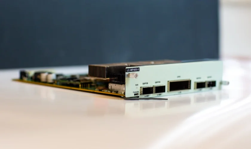
The QSFP (Quad Small Form-Factor Pluggable) module delivers high-speed transmission-typically 40 or 100 Gbps-via four parallel channels. These transceivers are widely used in backbone networks and integrate well with DWDM systems.
QSFP is commonly deployed in high-traffic data centres as it supports channel aggregation, offering high throughput in a single interface. It’s compatible with SR4, LR4, and PSM technologies, making it suitable for various distances and use cases.
XFP
XFP modules are used in 10G networks and are designed for higher-tier networking equipment. Unlike SFP+, they have a larger form factor. XFP modules are valued for their versatility and ease of replacement.
They are often used in carrier-grade networks due to their stable long-distance performance and support for a wide range of wavelengths, including CWDM and DWDM.
Installing SFP, SFP+, QSFP, and XFP Modules
Installing an SFP module is straightforward but requires attention, precision, and compliance with safety standards. Before installation, ensure module compatibility with your equipment and check the labelling. To avoid static discharge damage, use an anti-static wrist strap.
Installation Tips for SFP / SFP+ / XFP:
- Insert the module in the correct direction using the alignment guide – improper insertion may damage the port.
- Do not apply excessive force. If the module doesn’t slide in smoothly, it may be incompatible or dirty.
- Remove the protective dust cap from the optical connector before installation.
- After insertion, ensure the module is securely latched – you should hear a distinct click.
- Never touch the end face of the optical connector – any contamination may degrade signal quality.
For maximum safety and reliability, installation is best handled by professionals.
Connecting SFP, SFP+, QSFP, and XFP Modules
To connect an optical cable to an SFP module, use the appropriate patch cord (e.g., LC-LC, SC-LC, etc.). The patch cord must match the fibre type – single-mode or multi-mode.
Once connected, verify that the port activity indicator is on and run diagnostic commands to check the module status.
Always follow the manufacturer’s guidelines for connection – this ensures proper operation and minimises signal loss.

Removing SFP, SFP+, QSFP, and XFP Modules
To safely remove an SFP module, follow these steps:
Disable the port in your network device settings or power off the device to avoid electrical damage.
Disconnect the optical cable.
Gently pull the module latch or release ring, depending on the module design.
Remove the module in a straight motion – do not twist or pull at an angle.
Reapply the protective dust cap to the connector.
Store the module in an anti-static bag.
Note: Only remove and reinsert the SFP module when necessary, as frequent handling can wear out the port and degrade performance.
Understanding how to handle SFP module installation, manage PON systems, and work with transceivers is essential to maintaining a stable and reliable fibre optic network. Following these best practices helps prevent signal degradation, hardware damage, and network failures.